What is a Data Link Layer?
In simple terms, a link layer or the data link layer is the second abstraction layer in an Open Systems Interconnection (OSI) model. In computer networking, the down most layer in the protocol suite, that is, the connective framework of the Internet is known as the link layer. It is the collective methods and communications protocols that restrain a link that a host user is physically connected to. The link acts as the physical and logical that enables the interconnection among nodes or hosts across the network and a link protocol is a list of methods and regulations that supervise only adjacent network nodes of a network framework.
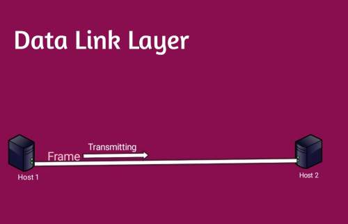
How does a Data Link Layer Work?
A data link layer works between two hosts that share a direct connection in a physical or logical sense. This direct connection could either be broadcast or point to point. Systems running on broadcast networks are usually located on the same common link. The working of the data link layer eventually gets even more complex when it deals with more than one host on a singular collision domain.
The data link layer is accountable for converting a data stream into signals with each passing bit and transmitting the output over to the targeted hardware. At the receiving end, the data link layer collects the data received, in the form of electrical signals, by the hardware, puts them together in a decipherable and easy-to-understand frame format, and passes it over to the adjacent upper layer.
Sublayers of a Link Layer
The data link layer consists of two sub-layers:
Logical link control sublayer
The topmost sublayer, LLC, deals with protocols that supervise the top of the data link layer, and additionally provide control overflow, error notification, and acknowledgment. The LLC produces addressing and lets you take control of the data link. It regulates the exact mechanisms required to be used to address stations via the medium of transmission and for monitoring the data interchanged among the source and recipient components.
Media access control sublayer
Media Access Control or MAC refers to the sublayer which determines who is permitted to access the media at any one use (e.g., CSMA/CD). However, it is otherwise referred to as a framework structure created based on MAC addresses inside. There are usually two kinds of media access control: centralized and distributed. Both of these may be employed to establish communication between people. In a network consisting of people conversing, i.e., a conversation, each of them will pause for a random amount of time before attempting to speak again, effectively creating a dragged and elaborate game of requesting “no, you first”. The Media Access Control sublayer is additionally responsible for frame synchronization, which determines the beginning and end of each frame of data inside the bitstream transmitted. It comprises one of the various methods: character counting, byte stuffing, bit stuffing, and timing-based detection.
Functions of a Data Link Layer
Framing & Link access
Data Link Layer protocols encompass every network frame inside a link-layer frame via encapsulation before the transmission that happens across the link. Each frame comprises a data field into which layers of network datagram are positioned and a decent amount of data fields. It determines the structure of the frame along with the channel access protocol by which the frame gets transmitted across the link.
Reliable delivery
Data Link Layer offers a reliable delivery guarantee. It transmits the network layer datagram sans any error. Robust and trustable delivery service is achieved through transmissions and acknowledgments. A data link layer primarily offers a reliable delivery service across the links as they possess higher error probabilities and can be debugged locally, by the link which results in an error instead of forcible retransmitting of the data.
Flow control
A receiver node can receive the frames at a rate faster than it can process the same frame. If there is no flow control, the receiver’s buffer is likely to overflow, resulting in a loss of frames. To overcome this situation, the data link layer makes use of flow control to restrict the sender node on one end of the link from overwhelming the receiver node on another end of the link.
Error detection
Errors can overrun your link due to signal convergence and noise. Data Link Layer protocol employs a methodology to detect one or more than so errors. This feat is accomplished by inserting error detection bits within the frame so that the receiver node can check for any error.
Error correction
Similar to error detection, error correction involves the receiver node not only detecting the errors but also evaluating the place of occurrence of the errors within the frame.
Half-Duplex & Full-Duplex
In a Full-Duplex mode, both nodes can the data simultaneously. In a Half-Duplex mode, only one of the two nodes can transmit the data at one time.
Addressing
The Data-link layer offers a layer-2 mechanism that addresses the hardware. The hardware address is generally assumed to be one of a kind on the link. It is encoded inside hardware when it is manufactured.
Synchronization
When data frames are transmitted back and forth across the link, both machines must be in perfect synchronization so that the transcanke place.
Multi-Access
When the host present across the shared link attempts to transfer the data, it runs a highly likely possibility of collision. The Data-link layer equips a mechanism such as CSMA/CD to make it capable of accessing common media across multiple systems.
Data link layer and resolving errors
The data link layer sets up an initial connection, that distributes the output data into data frames and manages the acknowledgments received from a receiver that the data has been received without any scope of error. It also makes sure that the incoming data has been received without a hassle through analyzing bit patterns located in special places in the frames.
If an error occurs, the data link layer lets higher-level protocols know that something unusual has occurred to the physical link. Frame sequencing possibilities across the data link layer allow the receiver device to rearrange frames that may have been transmitted without the correct sequence. The data link layer confirms the packet as unimpaired. The data link layer additionally supervises flow by allowing devices on a link to detect overflow. Nearby devices further transmit congestion data, so traffic can be rerouted suitably.
Error Detection
When data is transmitted from one device to another, the system provides no guarantee that the data received matches the data transmitted by another device. An error is an occurrence when the message received at the receiver end fails to match the message transmitted.
Types Of Errors are Following
Single-Bit Error
The only singular bit of the given data unit is modified from either 1 to 0 or from 0 to 1. The message which is transmitted is encrypted as single-bit, i.e., 0 bit is changed to 1. Single-Bit Error is unlikely to occur during Serial Data Transmission. For example, if a sender transmits the data at 10 Mbps, it indicates that the bit occurs only for 1s, and for a single-bit error to occur, a noise must happen for more than 1s. Single-Bit Errors are generally found in Parallel Data Transmission. For example, if eight wires are employed to transmit a byte if one of the wires happens to be noisy, single bit gets corrupted per byte.
Burst Error
The two or more bits are modified either from 0 to 1 or from 1 to 0 is called a Burst Error. The Burst Error is calculated right from the first to the last corrupted bit. The amount of time a noise lasts in Burst Error is more than the amount of time a noise lasts in Single-Bit. Burst Errors are more probable to occur in Serial Data Transmission. The number of affected bits is dependent on the data rate and how long the noise lasts.
Error Detecting Techniques Are Following
Parity Check
A singular extra bit is transmitted along with the original bits to produce an even number of 1s in case of even parity, or odd in case of odd parity. The sender, while creating the frame, usually counts the number of frames with the number of 1s in it. For example, if even parity is applied and several 1st result as even then one bit of value 0 is added. In this way, the number of 1s sustains itself as even. If the number of 1s turns out to be odd, it is modified to be even by adding one bit with the value 1.
Cyclic Redundancy Check (CRC)
CRC is a distinct approach to detect errors if the receiver frame comprises valid data. This methodology involves transmitting binary division of the data bits. The divisor involved is determined using polynomials. The sender evaluates a division operation on the bits to be sent and calculates the remainder. Before transmitting the actual bits, the sender adds the remainder to the end of the actual bits. Actual data bits added with the remainder are called the codeword. Hence, the sender transmits data bits in the form of codewords.